HITL & Avionics

Building the hardware-in-the-loop (HITL) table. This is standard in spacecraft design, so adopting best practices for boatcraft seems logical. Essentially, it’s a complete set of avionics laid out on a flat table. It goes by various names—flat-sat, non-form-factor build, vehicle-in-the-loop, HITL, etc. This setup allows software to be written and tested against real components under actual load conditions. Observing how your software stack handles edge cases, like power undervolt scenarios, is crucial. With everything onboard, I can easily place it on the roof for extended trials with the real solar panels and Starlink. We’ll also use this as a test environment for any software/firmware updates while the boat is at sea.
The system incorporates multiple communication channels and types:
GPS (I2C)
6DoF IMU (I2C)
3DoF Magnetometer (I2C)
Rudder Stepper (5V pulse/dir)
BLDC Propeller Servo Amplifier (UART, SPI, or analog)
MPPT Solar Controller (UART)
GoPro (USB)
Starlink (Ethernet/WiFi)
Motor Amplifier:
I initially went down a path that I had to reverse. I hoped to use the same Beckhoff EtherCAT system that many of my PLC/controls/test stands are built on. However, two key issues emerged, leading me to abandon that approach. I’m quick to pivot when a design or architecture shows signs of trouble—call it strong opinions, loosely held.
Problem #1: The Beckhoff modules required a baseline power draw of 2.1 watts just to operate the bus, plus 0.8 watts for each servo+stepper module. Losing 10% of power just to operate the communication layer isn’t ideal.
Problem #2: The setup process was excessively challenging. We vastly prefer the Codesys environment over the TwinCAT environment for several reasons, including ease of deployment in a lightweight Docker container on a Raspberry Pi. Unfortunately, this required going down to the register level for motor setup, debugging, and tuning. I spent a lot of time trying to get the motor to run in torque mode with a velocity limit, but not a velocity target. After 8 hours of wrestling with the state machine and its unhelpful fault messages, I began exploring alternatives.

Start of the week

End of the week
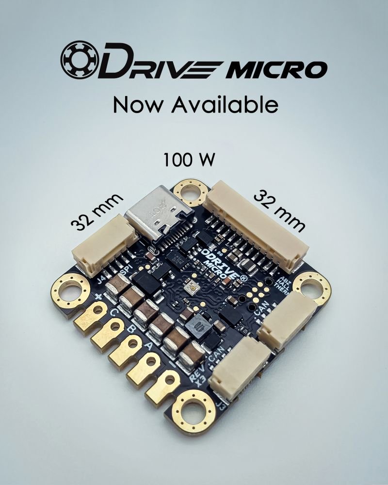
Odrive:
ODrive caught my attention as a more open-source, hacker-friendly option. I hadn’t considered them for past projects due to their lack of EtherCAT support, but in a simple UART-based application like this, they’re perfect. Not only were they cheaper with an online shopping cart (no quotes required), but they also responded to emails within a few hours. Their support engineer had even seen the boat mega-thread—what a small world!
FOC:
One key feature I needed was the ability to use FOC (Field Oriented Control) in a sensorless motor setup. FOC uses two PI controllers for the d-axis and q-axis currents, which are then converted back into three-phase voltages using inverse transforms. These voltages drive the motor's power electronics via Pulse Width Modulation (PWM), ensuring the stator's magnetic field remains optimally aligned with the rotor's field. The benefits include high efficiency, smooth operation, precise torque control, and reduced acoustic noise. FOC is widely used in applications like electric vehicles, robotics, and CNC machines where performance, efficiency, and dynamic response are critical.

The Motor:
Initially, I was considering a high-quality Tmotor drone motor. On paper, it looked perfect—right KV, robust matching ESC. However, my use case requires the motor to run for over 6,000 hours, well beyond Tmotor’s design expectations. The best they could estimate was around 800 hours mean-time-between-failure (MTBF). The motor's bearings were small, optimized for weight, but not for longevity.
I decided to revert to the reliable AutomationDirect motors, specifically their South Korea-based DC servo motors. I’ve used them successfully in past projects, and they’re built like tanks with no specific weight optimization. These motors have giant bearings and a 14mm output shaft, so I’ll sacrifice some energy in bearing drag, but the reliability is worth it. The MTBF is estimated at 30,000 hours.
My control strategy for this brushless DC servo motor is quite specific. I want to operate at a precise power target, without concern for position feedback mode. This requires a double-nested control loop: torque (current) as the inner loop, and velocity as the outer loop. Crucially, each can be capped at a configurable value, allowing me to cruise at 40 watts of real-time power consumption. The velocity achieved will simply be a byproduct of the torque loading on the prop. This approach, focusing on power level rather than velocity, gives me more predictable control over the energy budget. There’s still much to figure out regarding how the MPPT will balance energy from the solar cells versus the battery.

Why Sensorless?
Simply put, I hate encoders—the best part is no part. Since I have no requirement for position accuracy or even velocity ripple, I can afford to be loose with rotor position. Encoders are usually glass-etched disks with a photocell or magnetic analog hall sensors with a diametric magnet. While they’re standard in industrial CNC machines, I don’t want to risk failures in a 6,000+ hour saltwater and high-vibration environment. Fortunately, rotor position can be derived from the back-EMF of the motor coils, allowing the FOC algorithm to properly switch the FETs without an encoder. ODrive offers a beta version of this control, and after just 5 minutes of tuning, the motor was spinning smoothly!
Here you can see me removing the fragile glass absolute encoder from the AutomationDirect motor. To clarify, my plan is to retrofit a more rugged, lower-resolution encoder (borrowed from DoomScroller) onto the motor. This should provide 10x the reliability of the factory glass encoder. However, I want the motor controller to have the ability to fail over to a sensorless control scheme if/when the encoder fails. Maybe I’m being overly cautious, but I’ve seen enough encoder failures in much more benign environments…
Other misc updates.
Parts are starting to arrive. I’m begun to translate ya’lls generous donations to metal and electronics!
I’ve been chasing down mass properties errors in the CAD model, trying to get the CG/CB correctly positioned. Ensuring a self-righting design was made a lot harder with the addition of the Starlink Mast. The avionics pod had to be lowered by 2 inches. Current CG is right at the waterline. Current weight is 205lb.
The foam for the hull has been ordered. CNC in maybe 2 weeks?
Keels need to get ordered this week from SendCutSend.
Starlink has arrived!!! Now that I’ve got my hands on it, I can get CAD’ing on the enclosure. Open question whether I can put it in a radome or if the panel needs a clear view of the sky. I need to build a rocking rig to see how the pitch/roll affects upload rate.

