Battery Spine Fab Has Begun! Steel Is Real.
Battery Spine Fab Has Begun! Steel Is Real.
Fabrication of the custom 8ft long triclamp spool went great!
I’ve mentioned the Triclamp setup before, but I probably never elaborated on why I’m going this route. In short, I despise engineering custom seals. With all the off-the-shelf methods available, why reinvent the wheel? With everything else going on in this build, I wasn’t about to start designing bespoke flanges and digging through the Parker O-ring guide. The thought of using fiberglass to make a custom battery box which would then be submerged below the waterline was simply too scary. The triclamp ecosystem evolved to be dirt cheap because of the huge quantities from the food and beverage world. Everything has a 32ra finish, is laser welded, is stocked everywhere, and costs less than a cheeseburger.

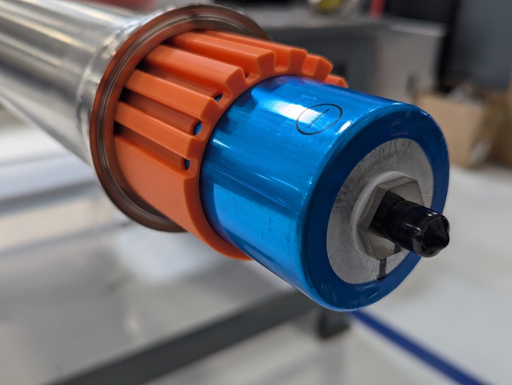
I chose the 3-inch Triclamp size because it’s the closest match to the largest cylindrical 60mm LiFePO4 battery on the market. With a 3D-printed liner, I can make up the diameter difference and route the power and balance battery wires back to the central BMS. It’s a super elegant solution: I get a sealed battery pod, a structural spine, a support mast for Starlink, and easy routing of electrical harnesses—all in one go.


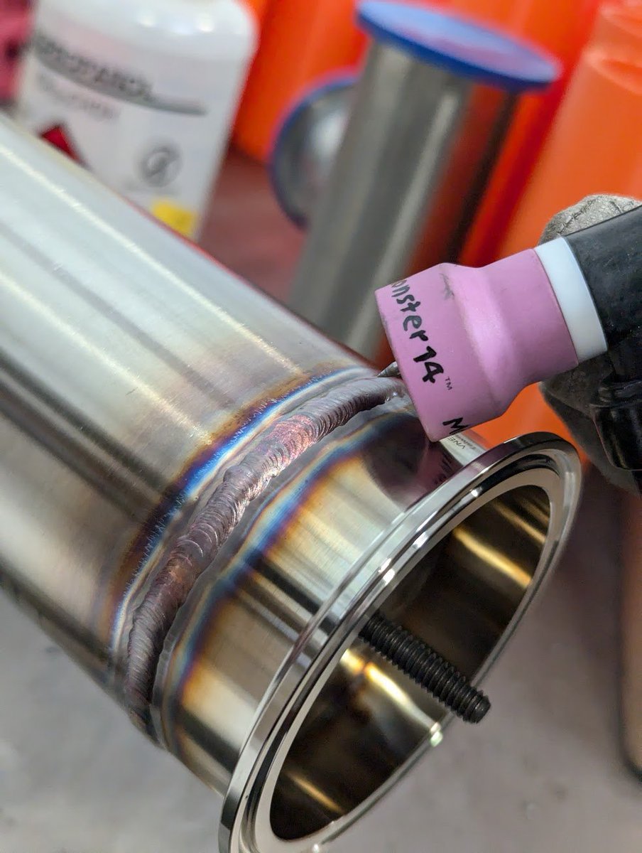
Of course, finding an off-the-shelf 8ft long 3in Triclamp spool wasn’t happening, so I had to weld my own from .065 sanitary tubing and flanges. Not the worst job in the world, but the welds need to be solid. Not only does the seal need to be airtight, but they’ll also be loaded in cyclic bending, so full penetration is a must. To avoid any blow-through on the ID, I machined a tight-fit plug to serve as a backstop and heatsink for the weld. It’s a trick I remembered reading about from the old Saturn V tank seam welding days, and it worked like a charm. Boat #1’s pod is done, but I ran out of argon gas before I could start on boat #2—next weekend’s project.

Tomorrow’s plan is to start wiring the cells. The giant LiFePO4 cells have a nice advantage—threaded studs, so no need for spot welding bus bars. I’ll use copper bus bars for the cell-to-cell connections, and everything will be torqued down with some red Loctite to keep things secure. I’m setting up the cells as two separate 6s1p packs. A single pack can absorb a full day of solar input, and having two gives us redundancy. If we lose a cell, we can simply flip the relay to string B and keep going.


The scale has finally sunk in. This is only 60% of the boat length. Transporting is going to be a non-negligible problem. It no longer fits in a pickup truck bed, at 14ft long. Might have to find a canoe or paddleboard trailer.
Speaking of fab, a round of @sendcutsend is on order. A huge thanks to@jimbelosic. Not only did he personally sponsor Project Bob, but he spent almost 3 hours last month telling the story of growing SendCutSend from the very first machine. His story is one that America needs more of, just a hard-working dude dedicated to making physical tangible goods. Keep it up!

We’ve got stainless keels, hanger brackets, G10 nose plates, copper busbars, and G10 Starlink box closeouts on the way. Honestly, having an easy waterjet option for the G10 is a lifesaver—I’ve milled that stuff in the CNC before, never again. Once these parts arrive, we can start assembling the servo motor, prop shaft, and bearings on the keel.
Hull geometry is now frozen!
Well, folks, we’ve officially left Hull-a-geddon in our wake. The CG is now sufficiently low, and after tweaking the waterline curvature, we’ve finally got our righting moment curves looking respectable. Big win there. The analysis tool I built was worth the effort, and it was pretty cool to see it churning through the STL files. For those who find themselves in the incredibly niche position of needing to perform stability analysis on hull shapes, you can check out the code here: Project Bob on GitHub
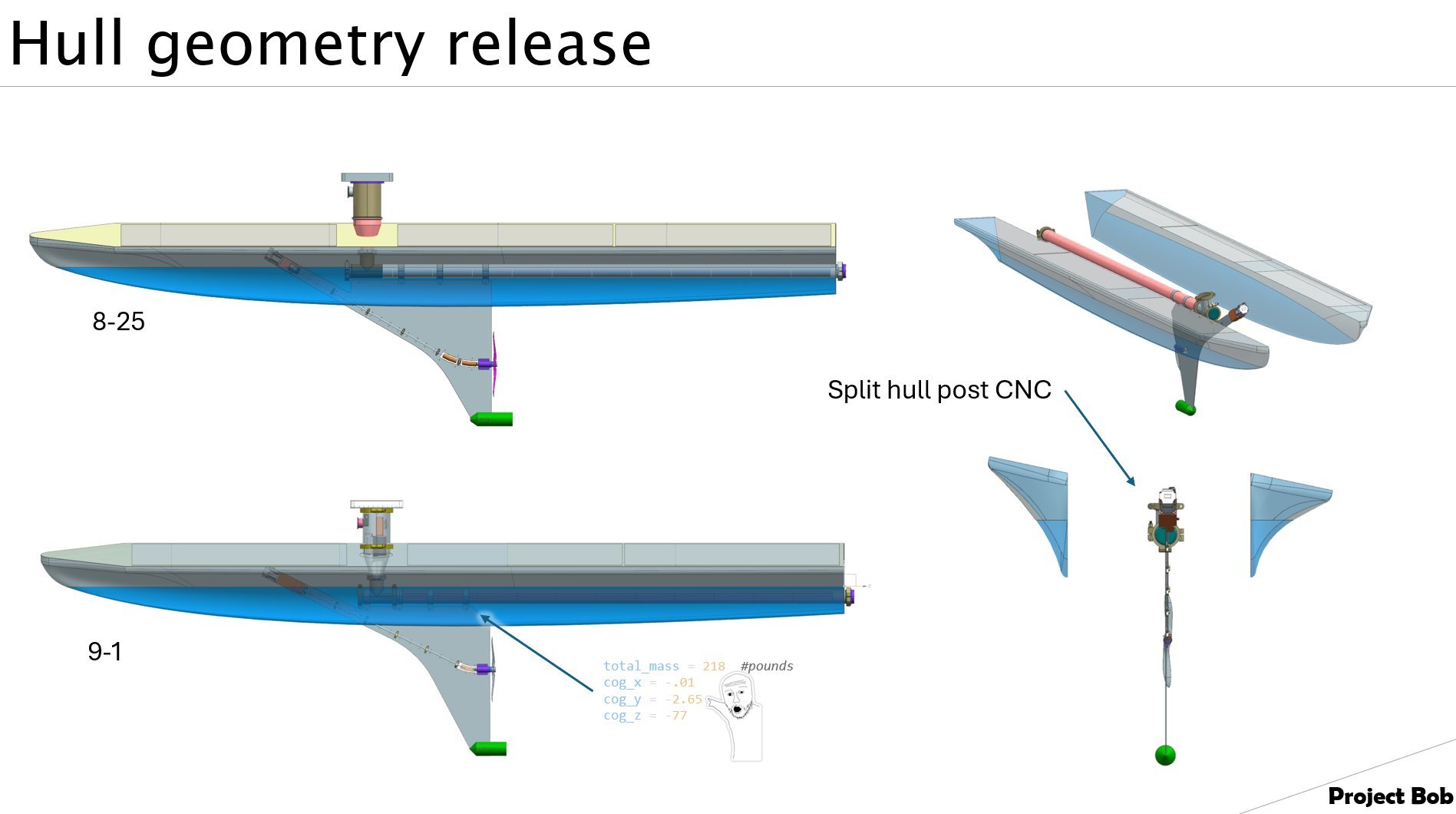

With the hull saga wrapped up, the geometry is off to the machine shop, and foam has been ordered—fingers crossed for delivery next week. Shoutout to a local shop owner following along on Twitter who offered up some time on his 22ft 5-axis router to machine the foam core of the hull. Talk about community spirit! Simplified the geometry down to a 3-axis part, but having that 5-axis head available for optimal approach angles is a nice bonus. Once the hull is CNC’d as a monolithic shape, we’ll slice it in half along the long axis to insert the spine and keel. It’s too tall for the vertical bandsaw, so I’m thinking a homemade hotwire cutter with some nichrome is in my near future.
Starlink Mast:
Finally made some headway on this. The original plan was to RTV the Starlink into a 5-sided box with the top dish surface exposed. But after digging a bit deeper, I realized I could transmit through an RF-transparent thin plastic skin. This lets me enclose the Starlink inside a thin-walled HDPE box, sealing the backside with G10. Bonus: I can hide the GPS and Iridium antennas inside this box too.
This weekend’s to-do list includes quantifying the uplink degradation I get from .04” HDPE or 1/16” G10. Stay tuned.

Save those dollars:
I can't thank ya'll enough for funding this project. Totally blown away by the support. I'm doing everything I can do to stretch the dollars! Below was a recent find on eBay. The specialty high angle high toque 17-4SS helical shaft coupler I'm using in the keel's prop shaft, 95% off.

Retrofit Time: Magnetic Encoders Installed
The retrofit magnetic encoders finally arrived from Phoenix. The reason for this retrofit is that the Automation Direct motors use an SSI (Synchronous Serial Interface) absolute encoder protocol, which isn’t compatible with the ODrive servo amplifier. This kind of issue is typical when mixing and matching servo motors and amplifiers from different brands—each seems to use its own protocol, making integration a headache.
For reference, here are some of the common protocols:
SSI (Synchronous Serial Interface)
BiSS(Bidirectional Synchronous Serial)
EnDat(Encoder Data)
HIPERFACE
You can see the old glass encoder below. The glass units have amazing resolution, sometimes as high as 21 bits per rev (2,097,152 counts per rev). Fortunately, mounting the new mag encoder to the motor was straightforward. Since I’m not concerned with extreme positional accuracy, a 2048-count magnetic encoder will suffice. I’ll make sure the entire motor assembly is sealed and waterproofed before bolting it onto the keel.
