Hulls and more hulls!
Time for another shareholder update. All of this is brought to you by the incredible generosity of Twitter. We’re breaking new ground with venture-backed hobbies. Shoutout to the top contributors!
@DanielMavlyutov
@tonsing (Caffeinated)
@ScottNorman (Earthrise)
@jimbelosic (SendCutSend)
@mov_axbx
133 days until launch! I’m targeting June 1, 2025. Because we’re totally solar-powered and making a massive change in latitude (LA @ 33° North to Cape Horn at 55° South), we need to leave at a specific time of year. Solar power changes dramatically with latitude and season, and as the old adage from Apollo 13 goes, “power is everything!”. As you can see from the graphs, we may need to shut down the Starlink in the Arctic Ocean to conserve power. The python analysis is super crude right now, but it gives us a ballpark on power budgets and helps inform the best launch date.

We’ll cruise for a significant stretch at southern latitudes. This is why the keel might look odd in some of the photos you’ve seen. Actually, the keel is perfectly straight in the water, but the upper deck with solar panels is intentionally tilted at a 20° angle toward the sun. This configuration improves solar efficiency during our southern latitude journey and provides an additional self-righting advantage should the vessel flip over (see the earlier post about hydrostatic righting moment for more details).
It’s starting to look like a boat!
We took delivery of the massive CNC’d foam hull last month. Big shoutout to Elijah for not only cutting it but also delivering it. The foam required 24+ hours of machining time! The material is 3lb density EPS foam, which strikes a great balance—lightweight but dense enough for clean cuts and a smooth surface finish.

The hull construction method we’re using is akin to building a surfboard. While there are plenty of approaches to fiberglass structures, this one is simpler and skips the need for a separate female mold. The first step was splitting the entire hull lengthwise to make room for the battery, spine, and rudder actuator. Given the hull dimensions—24 inches wide and 170 inches long—it was clear early on it wouldn’t fit in a vertical bandsaw. Enter the DIY hotwire cutter: nickel-chromium wire, a bookshelf, and some power supplies made for a classic engineering hack. There were a few hiccups, like snapping the wire multiple times during the process, but overall, it worked like a charm.


Once we had the two halves, the interior carving began. We needed precision here to create a conformal fit for the actuator and giant tube. For this, I turned to what may be the scariest Amazon tool I’ve ever purchased: a hot nichrome blade. It’s essentially an electrified ice cream scoop for foam, and was super effective. Unfortunately, the parting line was slightly off-nominal, resulting in a few depth errors and blowouts, but these were patched later with expanding foam.


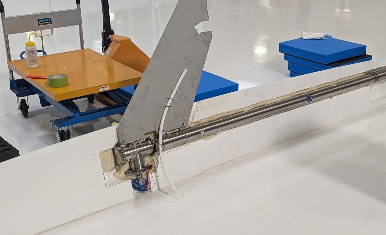
The rudder actuator is a beast. It’s an IP69K-rated (washdown grade) unit with stainless steel construction, using a stepper motor and ballscrew combo to drive a 6-inch stroke shaft. It’s rated for 200 pounds of force, though we’ll current-limit to less. I’ve always been a fan of overkill torque margins; friction changes over time, and you’d rather have too much power than too little. The actuator setup features a simple tiller arm design driven by a bell crank. With just one machined part (a bushing holder), the rest of the assembly leverages McMaster parts, SendCutSend components, and some TIG welding.


As for rudder sizing, I’ll be honest—it was a wild guess. The hull-to-rudder area ratio is approximately 1:145, placing it somewhere between a supertanker and a racing yacht. If the control authority ends up too low, we can weld an extension to adjust. Calibration and homing for the actuator remain open questions, but I’m leaning toward a robust hard-stop approach for simplicity and reliability. Just run it over to 45deg, let it stall, and set the angle. The reason we need a solution here is that there is no encoder, so after power cycles it'll have no idea what angle it initialized at, hence the need for a homing routine.
After carving, it was time to join the foam halves. We used 6lb density expanding foam to bond the interstitial spaces, keel, spine, and hull into one cohesive structure. This approach provides strong structural coupling. The stainless keel runs up to the spine for added strength, eliminating a common failure mode where a lead keel detaches and compromises stability. This design makes it virtually bulletproof, with the lead bulb securely bolted to a solid keel structure.


There were a few missteps along the way. The Triclamp clamps stuck out past the hull in some spots due to the parting line being slightly off. Expanding foam came to the rescue yet again, blending and smoothing everything out. If you’ve noticed the white tube in photos, that’s a conduit for power cables running to the prop drive system. Meanwhile, sanding took up an unreasonably large chunk of time—it felt like car bodywork. The 15-minute foam cure time was the silver lining, enabling quick progress with multiple cycles per hour.


Fiberglass Layup Time!
For the fiberglass layup, we opted for a wet layup directly onto the foam—no female mold needed. The process involved alternating layers of resin and cloth, with a lot of roller work to get the wrinkles out. We used marine-grade 4:1 resin with a slow hardener and 6oz twill fiberglass. All vacuum bagging supplies, including peel ply (a nonstick resin separator), polyester breather felt (a vacuum pathway), and Stretchlon bagging film (500% elongation), were sourced from FiberGlast. Sealing the keel penetration required extra tacky tape, which turned out to be one of the more annoying parts of the process. After chasing down inevitable vacuum leaks, we got a solid seal. Tomorrow’s unbagging will reveal the results, but even with minor wrinkles, function takes priority over aesthetics.


Cameras!
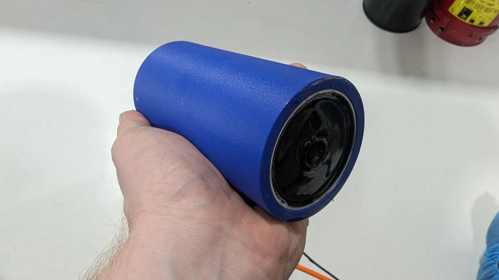
We’ve iterated heavily on the camera setup. Initially, we tested GoPros, but they were ultimately unsuitable for this project. The API is unreliable, and they struggle with long-term use. After much trial and error, we landed on TP-Link Tapo cameras. These cameras offer RTSP streams, excellent low-light performance, and solid reliability. The current configuration includes two forward-facing cameras, a rear-facing 360 PTZ camera, and an underwater camera. For the underwater unit, two big challenges arose: waterproofing and signal transmission. Water attenuates Wi-Fi heavily, so we opened up the PCB and got lucky: the designers used a u.FL connector and a Kapton Wi-Fi antenna. This allowed us to install a 3-foot antenna extension, running the signal above the waterline. Waterproofing involved three-step epoxy potting. Each component of the camera was carefully sealed, creating a solid brick of epoxy with only the glass lens exposed. It’s currently undergoing a month-long soak test and performing flawlessly. I’m optimistic this solution will hold up in real-world conditions.


Bob #2 Update!
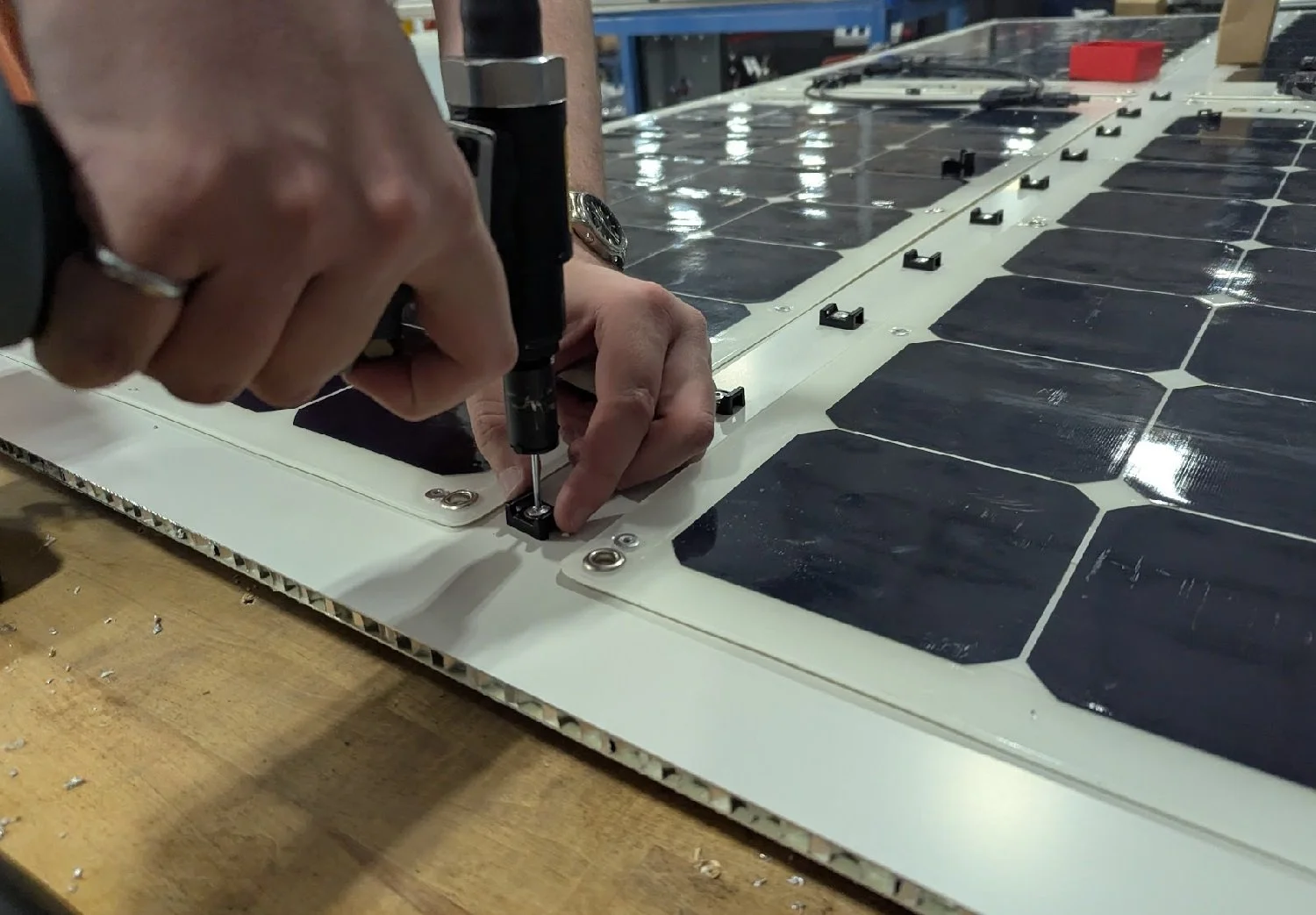
The second boat, Bob #2, is designed to handle more extreme conditions (think hurricanes). To save time and increase durability, we chose a rotomolded HDPE hull with a dense foam core. While heavier and less hydrodynamically efficient than Bob #1, this hull is nearly indestructible. Bob #2 also features doubled battery capacity (100Ah @ 24V) and an additional solar panel, bringing total output to 400W.


Construction on Bob #2 is progressing quickly. We’ve secured the aluminum honeycomb solar deck, riveted SunPower arrays, trimmed the hatch, and drilled anchor holes. The keel structure is ready for installation and will be riveted in place before the interior is backfilled with lightweight 2lb expanding foam, locking everything together. The solar deck and avionics box remain modular for transport.


Sea Trials:
I'm currently seeking permission to conduct trials in one of Los Angeles's reservoirs. A controlled environment like this would be ideal for safely running 24/7 tests without the risks posed by boat traffic or unpredictable conditions. If you have any connections or suggestions for securing access to a suitable reservoir, please reach out!
Once we have a testing location secured, we'll spend several weeks validating critical systems, iterating on software performance, testing telemetry, and evaluating the hull's structural integrity. Running laps in a closed body of water might not be glamorous, but it's the perfect sandbox for thorough debugging and optimization before any future ocean voyages.